
Remote Control Relay Module Infrared 5V 8-Channel High Low Level Trigger


£22.99
4 in stock
Infrared remote control 5V 8-Channel Relay Module

Dual Trigger design, using special two-way IC driver design- Anti-jamming capability, using freewheeling diode protection
- Part of the relay contacts using double-sided bold wiring to endure a larger
current through - 5.08mm high quality input and output terminals are used, and can be wired to a microcontroller for further control
- Inputs can be set high and low trigger, giving more flexible control
- Each relay has a LED to show the status for of the relay
- With 4 fixing holes to aid mounting the device.
Specifications:
1. Dimensions: 133 (L) * 55 (W) * 19 (H) mm;
2. The relay contact capacity: AC250V 10A DC30V 10A;
Product wired as follows:
1. VCC 5v: input supply power supply terminal
2. GND: input power is grounded terminal
3. Relay 1 to 8 trigger signal input is level is set by onboard jumper
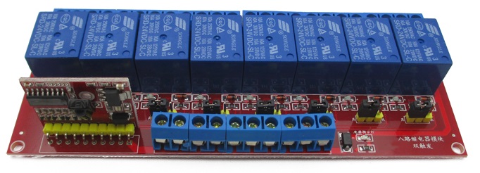
Some of the PCB is labeled in Chinese. So I will help describe the connections and jumpers.
With the Board facing you, i.e. the infra-red sensor at the front.
1) There are 10 blue screw terminals from Left to Right they are
VCC 5v
GND
CTR8
CTR7
CTR6
CTR5
CTR4
CTR3
CTR2
CTR1
You need to apply VCC 5v+ and GND to power the board.
External Trigger to Energise the Relay
Behind the 10 blue terminals there are 8 * 3pin jumper selection one for each relay. In the default position with the jumper across pin 1 and 2, while the external trigger on CTR8 to CTR1 is HIGH the relay will be energised. By placing the jumper across pins 2 and 3, then while the external trigger on CTR8 to CTR1 is LOW the relay will be energised. So by selecting the position of the jumper you can select the external trigger level High or Low to energise the relay.
Please note: For the relay to operate using the remote control function, the jumper must be left in the default position 1 and 2.
Behind the relays is a further row of blue screw terminals, 3 for each relay.
From Left to Right
NC, Com, NO for Relay 8
NC, Com, NO for Relay 7
NC, Com, NO for Relay 6
NC, Com, NO for Relay 5
NC, Com, NO for Relay 4
NC, Com, NO for Relay 3
NC, Com, NO for Relay 2
NC, Com, NO for Relay 1
(NC is Normally Closed contact, Com is Common and NO is Normally open contact)
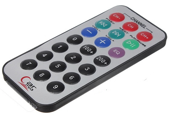
Remote Control Function. (Battery Not included)
Please ensure the jumper selection is in the default position 1 and 2
Pressing a number between 1 to 8 will energise the corresponding relay and REMAIN energised. Pressing the number between 1 to 8 again will de-energise the corresponding relay.
Press the number 0 will de-energise all the relays
Press the number 9 will energise all the relays
THE INFRA-RED SENSOR POINTS DOWN SLIGHTLY, DO NOT ATTEMPT TO STRAIGHTEN THIS, AS YOU WILL BREAK THE LEGS.
This item will be fully tested prior to despatch. Buy with confidence.
6) When upgrading to 1st class post, (if the option is available), please note this is sent via Royal Mail and is not a guaranteed next day service. If you need a 48hr service please select 48hr delivery at extra cost. This will be sent via Royal Mail or courier. I do not offer a 24hr service. No weekend or public bank holiday deliveries.
7) We attempt to send out all orders received before 10.00am. This excludes weekends and public holidays.
**** Important note **** Some sellers claim the stock is in the UK, please be careful, the seller is often in China and sends the item to a UK agent who then forwards the item on with a UK stamp. Check where the seller is located not just the item location. All my items are physically with me, here in the UK and I offer a quick delivery and communication within the UK.
During busy periods there maybe a delay in delivering your package by Royal Mail. I apologies in adavnce for any inconvenience but would like to point this out before you place your order.